The chip or flex-PCB antenna is only one part of the antenna system. Chip antenna + ground plane = antenna system.
In addition to that one antenna changes depending on the ground plane and the housing. With a Matching Circuit, this is then optimized.
Even if the antenna is perfectly matched, harmonics can occur with a bad power supply. Slots or holes in the board can act as antennas for harmonic waves. And there are hundreds of more reasons for errors.
The picture and shows a good Antenova Flex PCB antenna mounted in the case at different places. The antenna changes constantly and never become good because of the bad ground plane. In the end, the PCB was re-routed and the function was achieved.
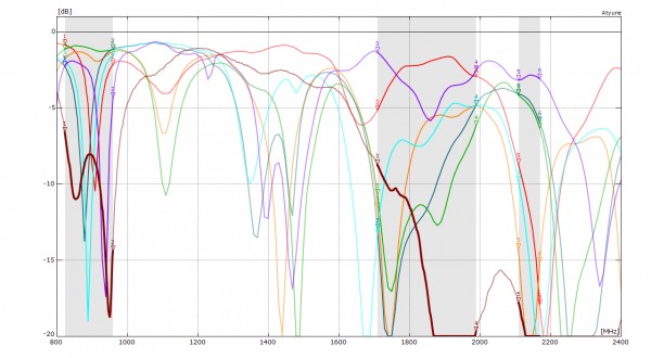
The grey zone in the graphic marks the GSM 850/900 band on the left, the GSM 1800/1900 in the middle and the UMTS 2100 on the right. The bold dark red curve was copied out of the datasheet into the graphic with the five tests we made. For the datasheet curve (all GSM bands and UMTS 2100 band) the Return Loss is always better than -6 dB. In theory, the ground plane of the IoT device is big enough, however, it contains at least two faults. The PCB with the wireless module has too many vias and the vias destroy the ground plane. The other problem is the misplaced U.FL connector on the main PCB (sorry, but I can not show the picture). The five other Return Loss curves show the measurement of the same PCB in the same enclosure. Only the flex PCB antenna was moved and placed at five different positions inside the enclosure. You will note that the Return Loss curves jump around. The light blue curve is the best compromise. At the GSM 1800 / 1900 band an estimated -6 dB return Loss was achieved. At GSM 850/900 the Return Loss curve is in the middle of the band but did not achieve -6 dB at the band edges. This result is common for monopole antennas on too small a ground plane. Moreover, the test shows that a monopole antenna is not a static component like a resistor and changes its parameters all the time when placed in different positions.


