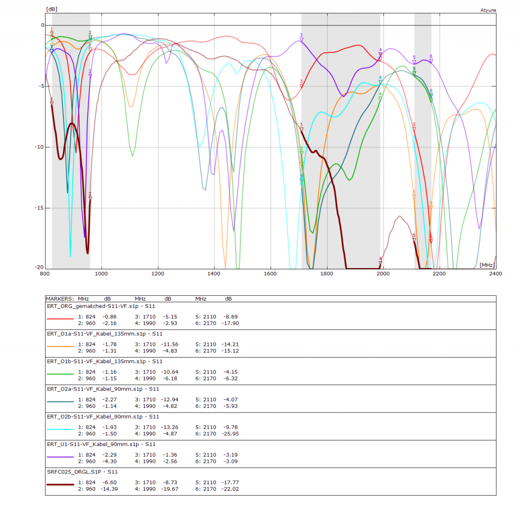
We tested a Flex PCB antenna from Antenova for a customer. The antenna was perfect but the ground plane of the customer was not. The thick red line shows the original curve documented by Antenova. The other curves show the return loss of the antenna at different places in the housing. After the customer re-routed the PCB, everything was okay. There is no optimal space available - this has to be determined in the measurement setup with the Vector Network Analyser.
The device under test is a Flex PCB antenna ( 71 mm x 13 mm) with coaxial cable and U.FL connector.
Here are the records of the cellular flex PCB antenna:
- Frequency bands: GSM 850/900 MHz, GSM 1800 / 1900 MHz, UMTS 2100
- Frequency range: 824 – 960 MHz and 1710 – 2150 MHz
- VSWR @ 824 – 960 MHz max. 2 and VSWR @ 1710 – 2150 MHz max. 2
Return Loss max. in all bands: -6 dB - Dimensions: estimated 71 x 13 x 0.15 mm
- Cable length: 150 mm
- Connector type: U.FL A right angle
The data sheet promises a Return Loss of better than -6 dB across all frequency bands.
GSM / UMTS flex PCB antenna – test in five conditions
- Antenna mounted inside a plastic enclosure at five different locations
- Antenna Return Loss stated on the datasheet for comparison
Some initial details:
- VSWR: 2 = Return Loss of -9.5 dB
- VSWR: 3 = Return Loss of -6 dB
You can calculate this yourself here http://cgi.www.telestrian.co.uk/cgi-bin/www.telestrian.co.uk/vswr.pl
A VSWR of 3 is the common minimum for embedded cellular antennas.
Flex PCB LTE antenna test
The grey zone in the graphic marks the GSM 850/900 band on the left, the GSM 1800/1900 in the middle and the UMTS 2100 on the right. The bold dark red curve was copied out of the datasheet into the graphic with the five tests we made. For the datasheet curve (all GSM bands and UMTS 2100 band) the Return Loss is always better than -6 dB. In theory the ground plane of the IoT device is big enough, however, it contains at least two faults. The PCB with the wireless module has too many vias and the vias destroy the ground plane. The other problem is the misplaced U.FL connector on the main PCB (sorry, but I can not show the picture). The five other Return Loss curves show measurement of the same PCB in the same enclosure. Only the flex PCB antenna was moved and placed at five different positions inside the enclosure. You will note that the Return Loss curves jump around. The light blue curve is the best compromise. At the GSM 1800 / 1900 band an estimated -6 dB return Loss was achieved. At GSM 850/900 the Return Loss curve is in the middle of the band, but did not achieve -6 dB at the band edges. This result is common for monopole antennas on too small a ground plane. Moreover, the test shows that a monopole antenna is not a static component like a resistor and changes its parameters all the time when placed in different positions.


