Step 1: Set dielectric constant to the FR4 specification (a typical value is 4.2 for FR4, we've made this the default value).

Step 2: Select your preferred units for measurement. We've set millimetres as the default, although you can choose mil if you prefer.
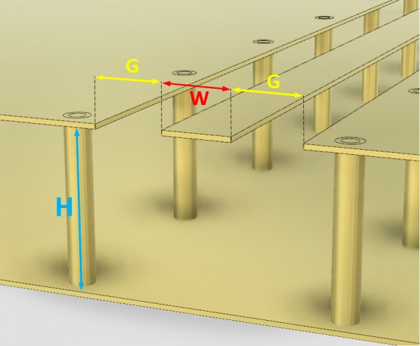
Step 3: Input the Height between the top layer and desired internal GND layer of your PCB. We've set the default value to 0.4mm, but make sure this is accurate for your design. The height of this is crucial for determining the optimal feed dimensions.

Step 4: Review the live results. Once you've input the values for the height and dielectric constant, the table and graph updates. The table provides dimensions based on 50 ohms, using nominal ranges for the size of the trace width and gap. If you wish to use smaller or larger traces, then you can use the cursor over the dynamic graph and select the dimensions that fit you design best.

Step 5: Review the graph. We've made this graph to show you acceptable tolerances (+/- 5 ohms) for a feed construction. Stay within these limits to ensure a good performing, low loss feed.


